
Titanic Trifles
- bryceggorrell
- Jul 23, 2023
- 10 min read

Updated: Jul 22, 2025
I wanted a project to challenge me into the next level of my rocketry hobby by creating things I’d never seen before.
I chose to bring to life Titan II, the largest and most powerful intercontinental ballistic missile (ICBM), ever deployed by the United States. Fortunately, deterrent weapon systems like Titan II have never been used, and thereby fulfilled their missions perfectly. My explorations into the history of Titan II and other aspects of the Cold War have greatly increased my understanding and gratitude for the brave people who’ve ensured the safety of the world during tense and perilous times. This project has turned out to be a gradually unfolding progression, beginning with the missile itself, and now includes a diorama of a launch complex with functional silo and other facilities, complete with lights, sound, and animation. I can give topside tours and share what I’ve learned, almost like owning a miniature museum.
This adventure began with the creation of a scale flying model. I built the first using only “old-school” techniques: turned balsa nose and motor mount, a few hand-drawn panel lines, and small wooden dowel rods for engine struts. Later, learning to create using 3-D CAD and a resin printer unlocked unprecedented capabilities for scale detail and reproducible accuracy. Uncounted hours spent studying photographs, technical drawings, and other resources gave me the confidence to portray later models of this mighty missile in every painstaking particular I chose to include. Prior to this project, I was only as advanced as some of the techniques shown in the third edition of the Handbook of Model Rocketry I had as a kid, published in 1970!


By basing my models around the commonly available BT-60 body tube, the missile’s diameter of ten feet (3.048 m) translated into a scale factor of 1:73.17, which for later purposes other than the missile itself I rounded to 1:72. This size tube allows for the use of a cluster of two 18 mm motors, with accurate placement. The center of pressure is moved appropriately aft by small polycarbonate fins, and the addition of ballast in the nose brings the total flying weight right up to 8 oz (226 g), the manufacturer’s maximum recommended all-up weight for two C6 motors. This makes my model lift off at the lowest possible safe and stable speed, for a spectacular photogenic launch. I used RockSim to predict the stability and other flight characteristics I wanted. The models are single stagers, recovered by parachutes in two separate parts. Due to the weight of the nose, I didn’t want to use a shock cord, but instead allow each half to recover separately, with negligible chance of collision. Actual apogee has never been measured, but they look like they reach 400-500 feet (120-150 m). Once I had a working example, I started to think about the captivating photos and videos I’d seen of full-scale test launches. Very impressive indeed is the spectacle of a 103 foot (31 m) tall missile rising out of the ground under full power.
00:00 - 00:23, Titan II in slow motion
The idea of making the launch look realistic introduced the exciting challenge of actually launching from an underground silo. As a successor to Atlas and Titan, Titan II was conceived to counter the problem of leaving missiles standing out in the open for many minutes as they prepared to launch. Inbound missiles were likely to arrive before the United States could mount any kind of defense, or have weapons that survived to retaliate, since missile sites were sure to be among the primary targets of a first strike. Using cryogenic oxidizers, those earlier missiles were stored dry, protected from attack in underground bunkers, then raised above ground for fueling and launch. Titan II was to be stored fully fueled, ready to launch directly from its underground silo on very short notice. Instead of fifteen, thirty, or even forty-five minutes of complete vulnerability, Titan II would lift off within sixty seconds of the command to launch, hurling the equivalent of nearly nine million tons (8,164,663 t) of TNT from each of fifty-four launch complexes clustered around Tucson, Arizona, Wichita, Kansas and Little Rock, Arkansas. The deterrent effect came from the terrible implications of having such thermonuclear fury always at the ready, capable of sending an overwhelming unstoppable retaliation, even perhaps while Soviet or other missiles were still in the air. These sleeping giants of assured destruction rested peacefully down underground, in fortified facilities designed to ensure survival through any but the most direct of impacts. Even if our entire country were destroyed in a preemptive strike, we could still pull down our enemy in return, making a nuclear war unwinnable, and therefore, unreasonable and undesirable.
Modeling an entire Titan II complex out past the perimeter fence at 1:72 scale would require creating a roughly square diorama, approximately eight feet (2.4 m) on a side. This would have similar requirements as a large model railroad layout, and would be too burdensome for me to store and transport. The solution came by designing the diorama into a glass topped coffee table, with the center of the launch duct concentric with a three foot (1 m) diameter round table. The diorama can be stored on the lower shelf inside the functional table, out of the way and on display. On flying days, the glass can be removed, and the diorama raised to the top level to form a stable platform, with space underneath to install the launch duct.


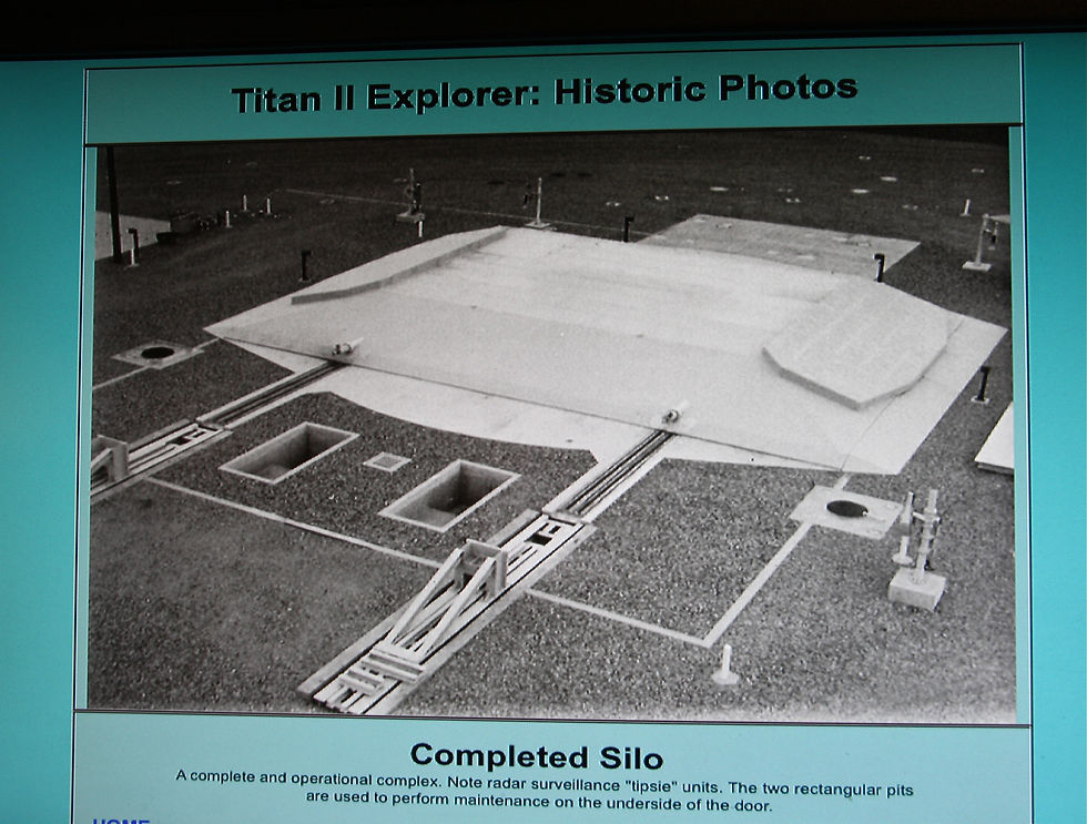
The challenges overcome by Titan II’s designers were staggering. The prospect of keeping a large liquid propelled missile ready to go at all times required innovations. Long term storage eliminated the possibility of using any cryogenic propellant. The chosen fuel, Aerozine 50, and oxidizer, nitrogen tetroxide, ignited spontaneously on contact. Their relatively stable characteristics meant they could be stored in the missile if kept in a reasonably controlled environment. Large air conditioning equipment, some of which is visible in a pit next to the silo door, kept the missile at a constant sixty degrees Fahrenheit (15.5 C).
Sound attenuation was another important consideration when launching from a confined silo. The noise created by the shattering roar of the first stage engine reflecting back on the thin aluminum structure would have destroyed the missile. This was solved by the placement of hundreds of boxes stuffed with sound absorbing insulation around the interior of the launch duct. Another important part of the solution was flooding the silo with 100,000 gallons (379,000 L) of water immediately before launch. The vaporization of the water absorbed large amounts of sound and heat energy, and released it harmlessly from the silo as large plumes of steam ejected through two vertical shafts at ground level.
My launch duct must accommodate an actual launch of a model rocket. The design is based on a piece of four-inch (10.2 cm) PVC pipe, with a stainless steel jet deflector to direct exhaust safely away. It uses a stainless eighth-inch (3.2 mm) launch rod, with its fifty-inch (127 cm) height matched to the ponderous performance of the rocket. I placed a piece of aluminum channel to form a rail vertically inside the duct. This guides the rocket’s fin opposite the launch rod, preventing the model from rotating about the rod and coming out of the silo facing the wrong way, or becoming jammed during launch.


The problem of simulating the blasts of steam from the exhaust shafts took a lot of thinking, and tuning by trial and error. I required a smooth, continuous blast of smoke that could be suddenly started on command. I considered several options, and eventually settled on an entirely electrical system. I built a machine that uses a smoke generator intended for model ships, which is enclosed in a large plastic container. When powered, the generator fills the container using recycled smoky air, building up a charge of thick white smoke. The smoke is held at bay until two computer cooling fans are activated, blowing the smoke along flexible tubing to the underside of each exhaust shaft opening. Short lengths of copper tube are fixed at twenty degrees from vertical to simulate what I have seen in photos and videos of Titan II launches. The smoke is sealed inside the container by check valves made from PVC pipe elbows and ping-pong balls, which are dislodged upward by the pressure drop caused by the fans. Air can then enter the container by flowing around the balls, as the smoke exits through the tubes. This machine makes it appear that the motors operate for a few seconds before launch, while building up thrust and awaiting the release of explosive hold down bolts.

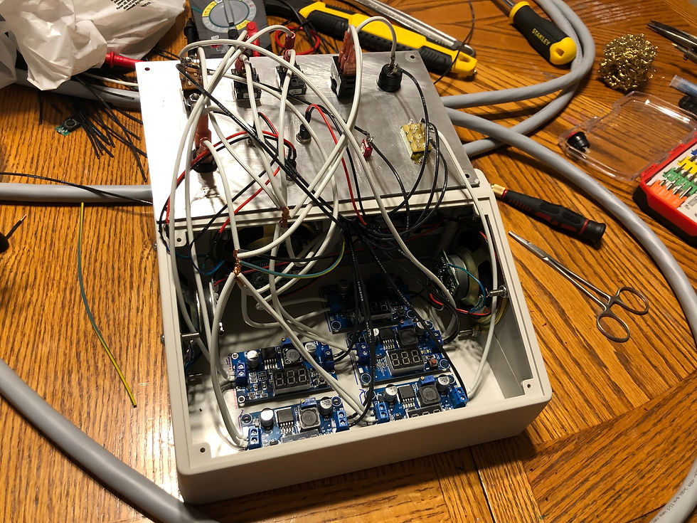
All systems are powered by a single sealed lead-acid battery providing twelve volts, DC. The control box contains several voltage regulators that feed off in different circuits appropriate to power the various functions. Everything can be easily unplugged from the control box for transportation and storage. The cable bundle gives a full twenty feet (6 m) between the operator and the silo, for a safe launch of the double C powered model.

During normal operations, the status light pole would glow green, with a yellow light shining through a blue lens. To offer visual cues as to scale, and for a more interesting diorama, I’ve included vehicles and figurines that portray a propellant transfer operation in progress. This is shown by the yellow light indicating a heightened state of caution for those on the complex, as toxic propellants were being handled. The rotating red beacon, used to indicate extreme danger such as a propellant leak or imminent launch, is simulated by four LEDs blinking in a sequence. This beacon and some other elements of the scene I obtained from a model railroad supplier.


As part of this Titan II resurrection project, I’ve also completed a separate launch controller for model rocketry in general. It is similar in appearance and functionality to the console located in each Titan II launch control center. It is complete with actual Roto-Tellite indicator units, retrofitted with LEDs replacing the incandescent bulbs. It performs a continuity check as part of an abbreviated model version of the launch sequence, which culminates in the simultaneous turning of two keys. The option of two people taking part in sending the rocket on its way is a lot of fun. Launch keys carried on separate lanyards can help kids (and grown-up kids!) simulate the Strategic Air Command’s two-man policy, and actually improves real-world safety at the range. (T-Minus Zero)
Played from speakers inside the control box are three different sound effect sequences: a civilian emergency alert, a launch order, and a launch. The civilian emergency alert simulates the experience of switching on a radio to listen to music as the Emergency Alert System is activated, broadcasting the sudden warning of an impending nuclear attack on the largest cities in the United States. It is anachronistic to the story of Titan II, considering that the last missile complex was deactivated in 1987, a decade before the EAS was implemented. Nevertheless, I use the sound effect sequence to introduce listeners to what they might hear today in the event of a nuclear attack, and to induce the fear and anxiety that affected generations of Americans. I created this sound sequence in 2021. In light of recent escalations of international violence and tensions, this sound effect is used only very carefully. It is a terrifying and stark introduction to a world we hope never to see.
The launch order sound sequence simulates what a missile combat crew would hear down inside the launch control center as they are ordered to launch their missile. It begins with a loud beeping sound to demand their attention. Then follows a repeated series of thirty-five alphanumeric characters. These characters would be copied into notebooks by two officers, as they hear them at their own workstations. They then trade books and review each other’s work. If their notes exactly match, they have authorization to open a safe containing authenticator cards. First, pairs of letters on the outsides of envelopes are matched to a corresponding letter pair transmitted as part of the order. If the letters on the card inside that envelope match more of the letters in the radio message, the order is authenticated. Encoded in the message would be additional information, including the time at which the crew is to launch. Also sent is a sequence of six letters used to unlock a butterfly valve on the missile that allows oxidizer to flow to the first stage. The six-letter combination is only kept with the President of the United States. This is a fail-safe that prevents any accidental or unauthorized launch. Assuming the order calls for an immediate launch, the Commander and the Deputy insert their own launch key into their console. These key switches are located too far apart for one person to turn them both. They must be turned within two seconds of each other, and held against spring tension for five seconds to start the launch. Once the key turn is complete, the launch sequence cannot be stopped. The silo door opens, triggering motion sensors above ground, and sounding an alarm bell in the control center. The red rotating beacon is activated and the Thunderbolt siren sounds a warning to those in the vicinity of an imminent launch.
The launch sound begins with the shrill scream of a turbopump spinning up to 24,000 RPM in two seconds, kicked into motion by an explosive start cartridge. The first stage engine immediately roars to life, providing 430,000 pounds (195,000 kg) of thrust to lift the 330,000 pound (150,000 kg) missile out of the silo and on its way to the target. Staging happens while the first stage is still operating, to ensure a positive g-load on the propellants in the second stage. The vents visible in the sides of the missile allow the second stage exhaust to exit the airframe without destroying the second stage. Following about five and a half minutes of powered flight, the reentry vehicle (RV) continues outside the atmosphere on a free-fall trajectory without any external guidance (or opportunity for jamming). All guidance inputs are established during the powered portion of the flight, hence a ballistic missile. After being backed away from the RV by small rocket motors, the second stage airframe reenters on a slightly different trajectory, acting as a large decoy. In addition, metallic balls are released to confuse any attempt at interception. A cloud of falling radar signatures would be seen, with the RV being only one of the pings. Around thirty minutes from launch, in a single flash, the incinerating power of a star would be unleashed at or near the surface of our planet as a fireball three miles (4.8 km) in diameter engulfs the target, the location of which is totally unknown to the missile crew. The devastation of nearly 900 square miles (2,331 sq km) would be complete.
It truly is ironic. If everything functioned perfectly in bringing about such destruction, Titan II would have failed in its mission of ensuring peace through quiet deterrence. Perched atop the miniature status light pole of my diorama is a tiny pair of doves, symbolizing the United States and the former Soviet Union. May peace prevail among all nations of the earth.
Many thanks to Chuck Penson for outstanding technical expertise and personal support, to Kelly Michals for excellent photography, and to the Titan Missile Museum in Sahuarita, Arizona for preserving and presenting the last Titan II complex. My deepest gratitude goes to those who served and sacrificed, some with their own lives, to ensure peace and stability during the Cold War, and those who continue today in doing so.
Resources
The Titan II Handbook: A Civilian’s Guide to the Most Powerful ICBM America Ever Built, Third Edition, Chuck Penson
Titan II: A History of a Cold War Missile Program, David K. Stumpf
https://www.flickr.com/photos/rocbolt/albums/72157631764194753


