
T-Minus Zero
- bryceggorrell
- Apr 16, 2023
- 8 min read

Updated: Nov 22, 2025
As I've learned through an explosive experience in 2003, fuses are for fireworks. (Not Quite a Dud)
We don't use fuses in model rocketry. We launch on command, at the end of a countdown, which can be paused at any point that something becomes unsafe, such as a gust of wind knocking over the rocket, perhaps pointing it toward the spectators, or because of a low flying aircraft approaching the flying field at the last second.
The launch controller is the device that supplies the electrical power to light the fire at the bottom of the rocket, causing it to launch at the end of the countdown, on command. It does this by heating a small wire to glowing white-hot, like the filament in an incandescent light bulb. The wire is dipped in something similar to a match head, creating a small burst of flame that ignites the propellant inside the rocket motor.
Launch controllers must be designed with features that ensure only authorized users can operate them. If someone prematurely gives the signal to launch while someone else is working at the base of the launchpad, a safety interlock prevents the firing signal from reaching the igniter, saving someone from painful burns, or at least from having to change their pants.
Typically this interlock includes a key of some kind, which is carried separately from the launch controller and must be inserted prior to the final action which completes the electrical circuit, such as the press of a button.
I had become pretty bored with the big red button I had included in my high school-era launch controller built from RadioShack components. A few years ago I realized I needed a new one to take my rocketry to a higher level.
I had been wanting a launch controller that uses only a key. I thought about using an old ignition switch from a car. This would allow the operator to insert the key, turn it "on" to arm the system, and then turn it all the way over to the "start" position to send the firing energy. Being spring loaded, the key would return from the "start" position to "armed" after liftoff.
In 2021, when my obsession with the Titan II missile system began in earnest, I had my answer:
Two keys!
With Titan II, a launch was initiated by the simultaneous turning of two keys, each against spring tension. These key operated switches were located far apart, so that two people were required to send the signal to the computer. Additional safeguards were in place, to ensure that not even Air Force personnel with knowledge of the system's inner workings could launch a rogue missile. The central safeguard was a secret unlock code, kept only with and sent only from the President of the United States as part of the order to launch. This code, a string of six letters of the alphabet, was entered by rotating lettered wheels, similar to a combination lock. Each wheel had sixteen letters from which to choose, making nearly seventeen million possible combinations. Only one would unlock a valve on the missile and allow propellant to flow to the engine. If a few incorrect combinations were entered, the unit would self-destruct, permanently disabling the missile.
My model launches don't require this level of security, but I did want to have some fun by pretending to follow a few aspects of a simulated launch.
With the generous technical support of Chuck Penson, a fellow Titan II enthusiast, I have created a magnificent model rocket launch controller, with a few actual vintage parts similar to those seen on the control panel of each Titan II launch complex.
-----
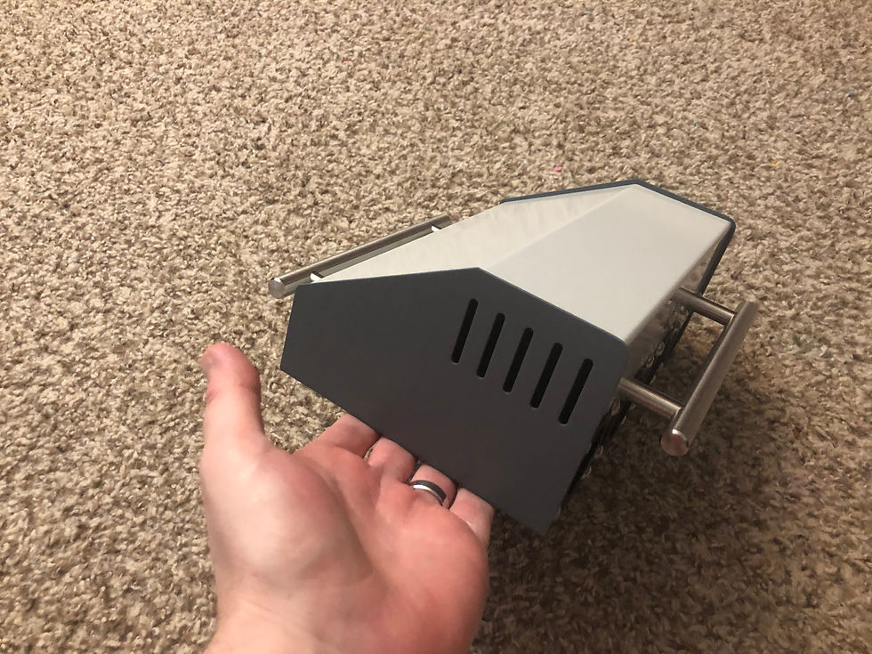
The case came to me almost ready to go. It is a purpose-built small metal enclosure, designed for electrical projects. It is made of only two pieces. The sides and bottom are a bent piece of steel, and the front, top and back are made of a single piece of aluminum. I added a carry handle to the front, and a similar structure to the back, also made from a large stainless steel drawer pull. The one on the back provides a place to wrap the firing leads, keeping them tidy when storing the unit.
The ends of the leads are attached to a quarter-inch headphone jack, allowing them to rotate without binding, and allowing me to change them out more easily than if they were hard-wired to the circuitry inside.


I had to cut a few holes in the aluminum to make way for the battery holders in the back, as well as the illuminated callouts and the two key switches.
The rectangular holes for the callouts and switches were cut with a Dremel and cleaned up and brought out to their final size and shape by hand filing.
The round holes in the back where the battery holders mount were cut using a really nifty technique I've learned. Into a solid piece of wood I drilled large round holes that exactly matched the size and location of those to be placed in the aluminum. I then drilled a smaller hole through the aluminum, inside each of the four locations where the larger holes would be placed.
This smaller hole was large enough to allow a carbide edged flush trim router bit to pass into. Clamping the aluminum tightly to the wood allowed me to run the router around in an increasing spiral, approaching the outside of the hole defined by each hole in the wood. When I got all the way out to the edge of the hole, the bearing on the router bit guided my hands around in a perfect circle, exactly matching the hole in the wood. The result is a beautifully clean machined hole in the aluminum, far better than drilling or any other method. Setting up on a milling machine and using an end mill or a boring bar would take a lot of time and effort to get right.
This technique followed a little practice I got with my airplane project, where I cut similar holes in the aluminum sheet that forms the floor of my fuel tank. I needed a place for a drain, and another where the fuel line exits to go to the carburetor. I had read online where guys were saying that modern carbide router bits can cut aluminum just fine. I must say, my first try in the fuel tank bottom, I went VERY slowly and tried to anticipate any dangerous jarring jumps from the router. This technique is a pleasure for working with thin aluminum sheet. You can cut almost any shape, if you can first make a smooth pattern in a piece of wood or other stable material.

The catch is that you have to smoothly rest your router on the aluminum sheet you are cutting. This might make for creative clamping to keep everything flush to the metal. In this case, it meant cutting the wood pattern block to the exact width of the aluminum sheet, so they both could be held together in the woodworking vise, with nothing sticking up to block the movement of the router. My full-scale CAD drawing can be seen in the photo above, which I used to mark the hole locations with precision.
The holes contain four battery holders, each of which keeps two D-cells. These eight batteries are wired in a way that allows three volts to be used to power the lights and alarm buzzer, and to perform a continuity check. This check ensures that electrical connections are intact by sending three volts down through the firing leads and right through the igniter, but with insufficient current to heat the igniter. When both keys are turned all the way over against their springs, the other bank of batteries is unleashed on the igniter, totaling twelve volts, which instantly lights the fire. The burning out of the igniter, a normal part of the launch, makes the continuity check fail to show a complete circuit after each launch, automatically silencing the buzzer and extinguishing the READY TO LAUNCH indicator.
Figuring out the wiring to accomplish the functions I wanted turned out to be a real brain bender for me. I have no formal training in electricity or electronics. I had to mentally work it out so that I had a launch sequence I liked. I'm giving you full access to my precious wiring schematic, if you want to build your own without going through all the painful trial and error I endured. It was a real relief when testing and it finally worked as I wanted!

The text of each callout is taken directly from the Titan II system, though modified in meaning for my model launch sequence.
BATTERIES ACTIVATED
In Titan II, this confirmed that electrolyte solution was being pumped into batteries on board the missile, which sat dry as the missile awaited launch.
ADVANCE TO READY
This callout was part of the guidance system of Titan II. In my sequence, it lets me know that only the first key is turned, and that the readiness check depends on the second key being turned one click.
DC PWR SUP 2 ON READINESS
In Titan II this showed that a backup power supply was online. My model sequence implies that the second bank of batteries is ready, which is used to boost the current up to the level needed for ignition.
On the second key turn, the unit runs three volts through the firing leads as a continuity check, illuminating the READY TO LAUNCH callout, and sounding the buzzer, if electrical connections are intact. Turning both keys simultaneously sends twelve volts down to the rocket, to achieve ignition.

The callouts are manufactured parts called Roto-Tellites. These were used extensively in missile systems and NASA launch control centers, in addition to other industries where automation assisted with old-school electromechanical equipment.
The "Roto" in their name comes from the ability to spin them around while in the console, without having to remove the unit or access it from the back of the panel. This is because they use small incandescent light bulbs to illuminate the text, which burn out and must be replaced eventually.
I think they look fantastic, by allowing the text to be read without them lit, and then lighting from the back through filters, glowing different colors from their uniform white appearance when unlit.


Credit goes to Chuck Penson for giving me the name of this device and helping me find the right font for the text, allowing me to recreate the exact appearance of real Titan II equipment. To create the text, I printed black ink on transparency sheet, and cut them out to size.
Prior to Chuck's intervening "enlightenment" (I couldn't resist), I was planning on having to build something from photos of a launch control center console. I had never even considered the possibility of finding real Roto-Tellites available. I found mine "new old stock," in their boxes, on eBay from a seller in Israel.
I retrofitted each callout to run on three volts, instead of the twenty-eight volts of the typical military equipment from the 1960s. This retrofit was accomplished with small board-mounted LEDs from SparkFun. The individual units, complete with appropriate resistors, are made to sew into clothing for creative projects like a biking outfit with illuminated turn signals sewn right into the fabric.
They come in strips of five units, attached together, which normally would be broken apart. I left mine together and wove and soldered a wire lead into each positive side, and another through the negatives, so they run in parallel. A little adjustment of the height of the strip by sanding made them fit just right into the old Roto-Tellites, which had corresponding slots cut into them by Dremel. The arrangement worked out beautifully, with a nice, even row of LEDs right through the center of each little window.


Since model rocket flying is best when done in a group, this controller increases the enjoyment by allowing two people to take part in a launch. Each have to turn their required key. When flying with a bunch of kids, having two keys helps maintain order and enhance the adventure, by assigning a Commander and a Deputy Commander for each launch.
As part of Uranium, a historical science documentary, the following video was filmed at the Titan Missile Museum in Arizona, the only remaining Titan II launch complex. Our very own Chuck Penson explains the process of receiving, verifying and carrying out a launch order to Derek Muller, of YouTube's Veritasium channel.
Here's a simple video showing me going through a test firing:
It's a lot of fun turning those keys instead of pressing a button.
Interested in safe hobby rocketry? Check out:
Happy flying to you!


